

What Is a VFD in a Pump System?
A vfd pump drive regulates electric motor speeds across centrifugal pumps, booster sets, and hydronic circulation systems by continuously modulating electrical supply frequency and voltage. Wired between the electrical supply and the three-phase pump motor, it alters rotational velocity to maintain constant discharge pressure and optimal hydronic efficiency.
While fixed-speed pumps waste immense electrical energy by pumping against throttled discharge valves or cycling on and off, a variable frequency drive electronically varies impeller speed to match instantaneous hydraulic demand.
In any pumping installation, the drive is wired between the electrical supply and the three-phase pump motor. It does not replace the physical pump volute, mechanical seal, piping, or pressure expansion tank. Instead, adding an external vfd pump controller eliminates mechanical throttling valves, prevents destructive water hammer on check valves, and suppresses pipe vibration across commercial and industrial fluid networks.
How Does a VFD Control a Pump?
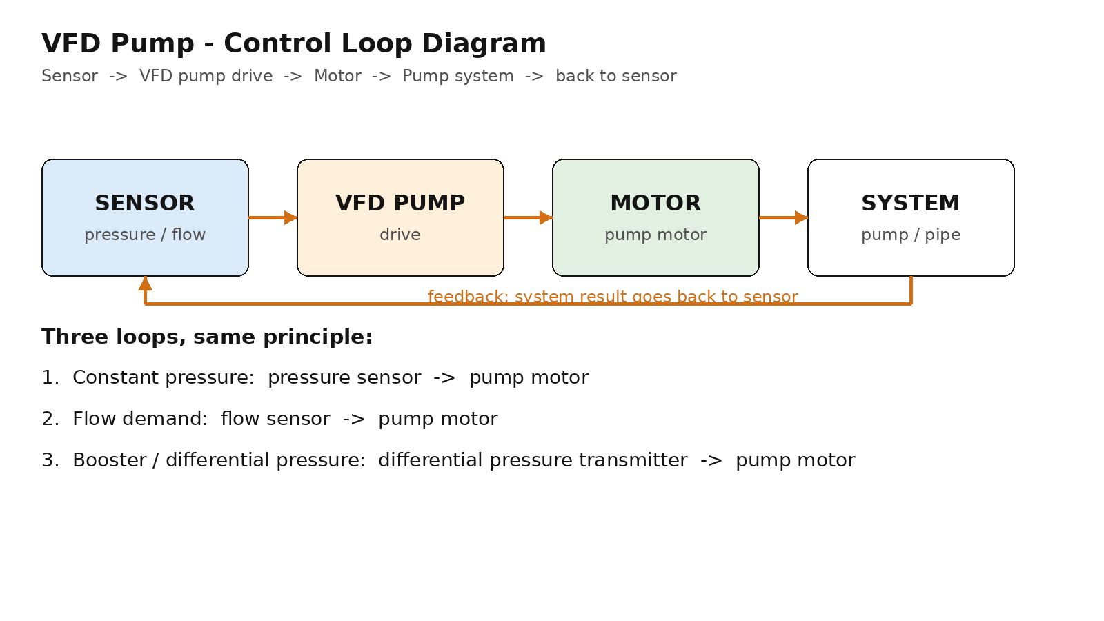
A VFD regulates pump flow and head through a continuous three-stage electronic conversion process coupled with closed-loop pressure feedback:

Input AC Rectification:
Incoming alternating current from the utility feed passes through an input bridge rectifier, converting fixed-frequency AC voltage into direct current (DC).
DC Bus Energy Buffering:
The DC bus capacitor bank filters ripple voltage and buffers electrical energy, allowing the drive to maintain smooth voltage regulation even during sudden load changes.
Inverter PWM Synthesis & Closed-Loop Regulation:
High-frequency IGBTs synthesize three-phase AC power at the exact frequency commanded by the internal PID controller. The drive compares pressure transmitter feedback against the programmed setpoint, speeding up the motor during high demand and slowing it down when valves close.
An analog pressure transmitter located on the discharge header provides the real-time feedback signal that keeps line pressure constant.
Why Use a VFD Pump? Core Engineering Benefits
Installing variable speed control on pump systems delivers substantial electrical, mechanical, and hydraulic advantages:
- Soft Starting & Complete Water Hammer Elimination: Direct across-the-line pump starting causes massive hydraulic shockwaves (water hammer) that rupture pipe joints and damage check valves. A VFD ramps pump acceleration and deceleration smoothly over 10–30 seconds, maintaining laminar flow.
- Cubic Affinity Law Energy Reductions: Centrifugal pumps obey the affinity laws: flow varies with speed (Q ∝ N), head varies with speed squared (H ∝ N²), and power varies with speed cubed (P ∝ N³). Operating at 80% flow drops power consumption by ~50% compared to full-speed throttling.
- Precise Constant Pressure Regulation: Holding discharge pressure steady regardless of fluctuating consumption prevents pipe overpressurization, reduces valve wear, and guarantees constant water pressure across all delivery fixtures.
- Cavitation Suppression & Mechanical Seal Protection: Modulating pump speed prevents excessive suction velocities that trigger impeller cavitation, drastically extending the service life of mechanical seals and motor bearings.
Where Are VFD Pumps Used? Key Hydronic Applications
Variable frequency drives are deployed across diverse commercial, industrial, and municipal hydronic networks:
- Commercial Booster Pumping Systems: Multi-story commercial complexes and residential high-rises utilize booster pumps equipped with dedicated sleep/wake macros (PP-01 = 30) to maintain constant fixture pressure during peak demand while putting drives to sleep during zero-flow hours.
- HVAC Chilled Water and Heating Circulation: Central hydronic loops regulate secondary chilled water pumps based on differential pressure across the most hydraulically remote air handler coil, directly complementing commercial VFD HVAC air handlers and industrial ventilation fans.
- Cooling Tower Water Circulation: Condenser water pumps modulate flow across heat exchangers and chiller evaporators, synchronizing with tower fan speeds to preserve optimal approach temperatures.
- Agricultural Irrigation and Deep Well Pumps: Variable speed drives protect long rural pipelines from burst pressure and allow three-phase submersible pumps to operate smoothly from rural utility lines, pairing naturally with a single phase to 3 phase VFD when three-phase service is absent.
Engineering Checklist: How to Select a VFD for a Pump
Follow these four engineering verification steps when sizing and configuring a pump drive:
Inspect the Pump Head-Flow (H-Q) Curve:
When a VFD slows a centrifugal pump, the entire H-Q curve moves downward and leftward. Ensure the operating point at reduced frequency remains within the pump manufacturer’s Recommended Operating Range (ROR) to avoid deadhead overheating.
Verify Static Head vs. Dynamic Head Limits:
In pumping systems with high static lift (e.g., deep well or high-rise boosting), the pump must generate sufficient head to overcome elevation before any water flows. Program a minimum speed limit (typically 25–30 Hz) to prevent zero-flow impeller churning.
Match Nameplate Full Load Amperage (FLA):
Select the drive continuous output current rating to meet or exceed motor nameplate FLA at maximum continuous duty. Never downsize the drive based on kilowatt ratings alone.
Configure Dedicated Constant Pressure Sleep/Wake Macros:
In booster applications, activate Epsivo constant-pressure water supply macro PP-01 = 30. Set the sleep frequency (e.g., 25 Hz) and sleep delay timer so the drive stops cleanly when all taps close, waking automatically when header pressure drops below the wake threshold.
Always verify static head vs. friction head before lowering minimum pump speed, ensuring the pump maintains sufficient velocity to lift fluid.
Epsivo VFD Series for Pump Applications
Epsivo manufactures engineered variable frequency drives with specialized firmware macros for constant pressure water supply and hydronic loop control:
| Series | Platform | Power Range | Input Voltage | Pumping Suitability & Hydronic Fit |
|---|---|---|---|---|
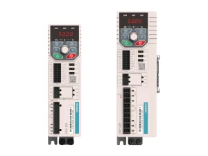 ES210 | Single-Phase Compact VFD | 0.4–2.2 kW | 1-Phase 220 V in, 3-Phase out | Dedicated constant-pressure water supply macro (PP-01 = 30), single-phase input to three-phase booster pumps for residential and light-commercial pressure boosting. |
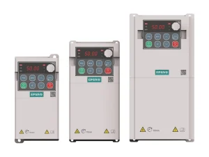 ES230 | Compact Multi-Function | 0.4–11 kW | 220–240 V / 380–415 V | Multi-function compact drive with built-in constant-pressure water supply macro (PP-01 = 30), integrated sleep/wake thresholds, and analog pressure transducer inputs. |
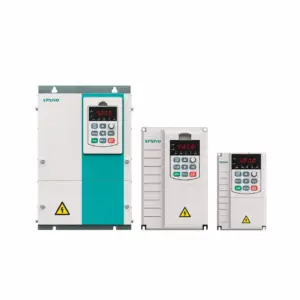 ES300 | Sensorless Vector VFD | 0.75–710 kW | 3-Phase 380–415 V (±15%) | Sensorless vector workhorse for heavy industrial pumps, municipal transfer stations, irrigation booster arrays, and chemical circulation loops. |
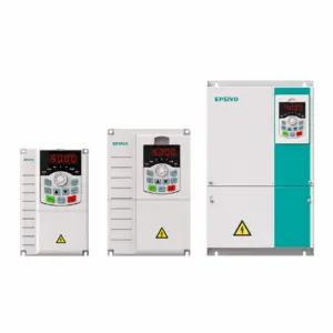 ES500 | High-Performance Vector | 0.75–710 kW | 3-Phase 220–240 V / 380–415 V | High-performance vector drive with adaptive PID regulation, multi-sensor feedback, and advanced hydronic fault monitoring for critical industrial pumping. |
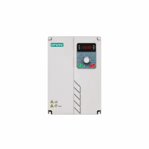 ES530 | Through-Wall Mount VFD | 15–400 kW | 3-Phase 380–415 V (-15%~+10%) | Through-wall mounting with external heatsink isolation, ideal for clean pump rooms and high-power hydronic pumping stations. |
For ES210, ES230, and ES530 models, constant-pressure sleep and wake parameters are pre-configured in macro PP-01 = 30 (Manual §4.4).
Frequently Asked Questions About VFD Pump
What is a VFD pump and how does it work?
A VFD pump is a centrifugal or positive-displacement pump controlled by a variable frequency drive. It works by converting incoming AC utility power into DC, smoothing it on the DC bus, then inverting it into variable-frequency AC. The internal controller monitors pressure or flow feedback from a field sensor, adjusting motor speed continuously so that pump hydraulic output precisely matches real-time demand.
Can you put a VFD on any pump?
Most centrifugal, turbine, and screw pumps can be driven by a VFD, but specific engineering checks are required. You must verify motor insulation rating (Class F or inverter-duty rated), check whether high static head requires a minimum operating frequency limit (preventing deadheading), and confirm that positive displacement pumps are sized for constant torque with adequate lubrication at low RPM.
What are VFD constant pressure pumps?
The term typically refers to a complete booster pumping package that integrates an electric pump, a variable frequency drive, and a pressure transducer. While packaged pump suppliers sell the entire skid assembly, Epsivo manufactures and supplies the electronic drive component itself. Our ES210, ES230, and ES530 series feature dedicated constant-pressure firmware macros (PP-01 = 30) for seamless integration with third-party pressure sensors and hydronic skids.
How does a VFD control a pump in a closed loop?
The drive establishes a closed Proportional-Integral-Derivative (PID) loop. An analog pressure transducer mounted on the water discharge pipe transmits a 4–20 mA or 0–10 V signal to the drive. The drive compares this measured pressure against the programmed target setpoint. If pressure drops due to opened taps, the drive ramps frequency up; as taps close, the drive decelerates the pump and enters sleep mode if flow ceases.
How do you read a pump curve with a VFD?
A pump performance curve displays flow rate (Q) on the horizontal axis and pressure head (H) on the vertical axis. The system resistance curve intersects the pump curve at the operating point. When a VFD reduces motor speed, the entire pump curve translates downward and toward the left. The new operating point represents lower flow and lower discharge head, reducing power consumption by the cube of motor speed according to the affinity laws.