
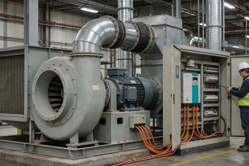
Opening: A Drive for a Fan, Not a Fan for a Drive
A vfd fan drive controls electric motor speeds across industrial fans, commercial blowers, and air handling equipment by altering electrical supply frequency and voltage. Epsivo manufactures and supplies standalone variable frequency drives that regulate fan motors—we sell the electronic drive controller, not the physical fan assembly.
The marketplace presents three distinct search intents around fan speed control: packaged fans pre-fitted with integrated motors, standalone VFD drives engineered for fan control, and internal cooling fans built inside a drive enclosure. This technical guide focuses exclusively on standalone variable frequency drives applied to fan motors.
Rather than running a fan continuously at full nameplate speed while mechanically restricting air ducts with dampers, installing a variable frequency drive dynamically matches fan CFM to real-time system demand. If your facility operates existing fans, you rarely need to replace the housing or impeller. Adding an external vfd fan drive to the three-phase motor modulates speed from sensor signals or automation commands based on airflow, static pressure, and motor nameplate ratings.
What Is a VFD Fan Drive?
A variable frequency drive controls an AC electric motor by modulating the frequency and voltage of the electrical power supplied to it.
In a fan control system, the drive sits electrically between the incoming utility power supply and the fan motor. It does not replace the fan, motor windings, or ductwork. Instead, it electronically alters motor rotational speed, and motor speed directly dictates airflow (CFM), static duct pressure, and aerodynamic noise levels.
While a fixed-speed fan spins at full speed whenever energized, a drive-controlled fan modulates continuously to deliver precisely the volume of air required by the ventilation process, eliminating wasteful mechanical throttling.
How Does a VFD Control Fan Airflow?
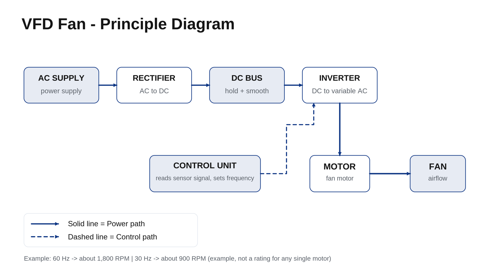
A VFD fan drive regulates airflow through three sequential power stages governed by fundamental aerodynamic affinity laws:
Input Rectification and DC Bus Smoothing:
The rectifier converts incoming AC power into DC, while the internal DC bus capacitor bank filters ripple and stores energy, providing a stable DC voltage for inversion.
Inverter PWM Synthesis and Closed-Loop Control:
High-speed IGBTs invert DC back to variable-frequency AC. The processor reads sensor signals—such as duct static pressure, temperature, or CO2—and calculates the precise frequency needed to maintain target conditions.
The Fan Affinity Laws and the Fan Curve:
Fan performance follows cubic aerodynamic relationships: Airflow varies directly with speed (CFM ∝ N), static pressure varies with speed squared (SP ∝ N²), and power consumption varies with speed cubed (HP ∝ N³). Slowing the fan shifts the operating point to lower airflow and dramatically lower power draw.
Reducing fan speed by 20% drops electrical power draw by nearly 50%, making speed reduction far superior to mechanical air damping.
VFD vs Damper vs Motor Starter: Control Methods Compared
Airflow can be restricted mechanically or modulated electronically. The engineering comparison below highlights key trade-offs:
- Across-the-Line (DOL) Starters: The fan runs at full 100% speed at all times. If less airflow is required, excess air must be dumped or motor run hours must be cycled. Inrush current reaches 600%–800% FLA, causing high electrical demand spikes and mechanical belt wear.
- Mechanical Inlet Guide Vanes / Outlet Dampers: The fan motor runs continuously at full nameplate speed while dampers choke ductwork to restrict air delivery. Choking generates turbulence, acoustic rumble, and excessive fan backpressure, consuming 70%–80% power even at 50% airflow.
- Variable Frequency Drive (VFD): Motor speed slows to match required CFM. Noise plummets, duct static pressure stabilizes, inrush current is limited to 110% FLA, and electrical power follows the cubic affinity curve, dropping to ~12.5% power at 50% flow.
When Is a VFD the Right Choice for a Fan?
A VFD fan controller delivers outstanding payback across ventilation applications with fluctuating flow requirements:
- Variable Occupancy Ventilation & Commercial AHUs: Buildings operate with varying occupancy. Drives modulate supply and return fans in [commercial HVAC systems](/vfd-hvac/) based on real-time CO2 and thermal loads, eliminating over-ventilation.
- Cooling Tower and Heat Exchanger Fans: Cooling tower fans modulate RPM against ambient wet-bulb temperatures to hold condenser water setpoints, pairing with [chilled water pump controls](/vfd-pump/) for total plant optimization.
- Soft Starting and Mechanical Stress Reduction: Large diameter industrial fans have high rotational inertia. Starting across-the-line snaps drive belts and strains shafts. A VFD accelerates the fan over 30–60 seconds smoothly.
- Acoustic Noise Reduction in Sensitive Zones: Aerodynamic fan noise is directly tied to blade tip velocity. Slowing fan speed by 20% achieves a noticeable drop in sound power levels across offices, schools, and hospitals.
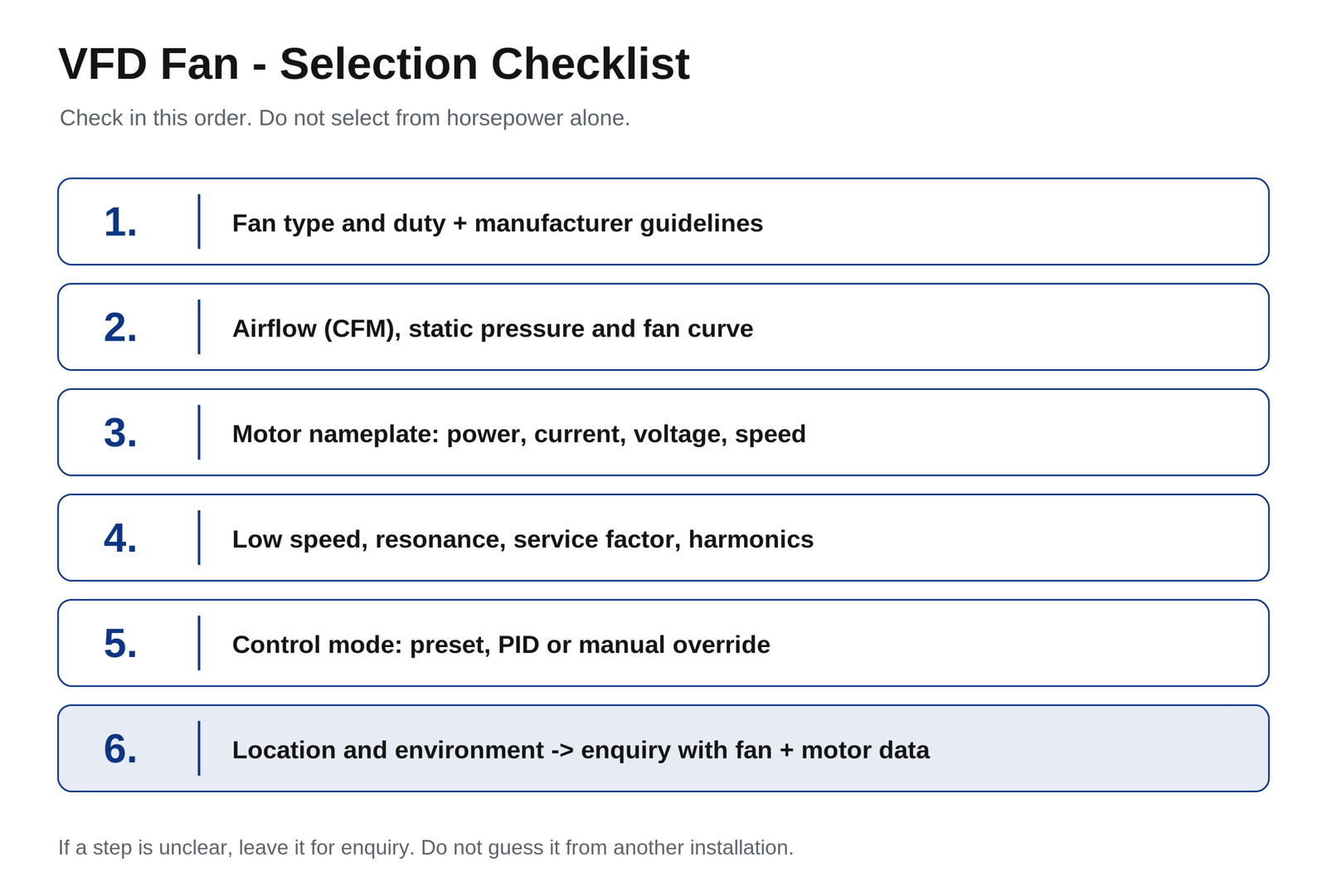
How to Select a VFD for a Fan: A Six-Step Guide
Use this six-step engineering checklist to specify the correct drive model from your motor and fan parameters:
Check Fan Type, Airflow, and Static Pressure:
Confirm whether the equipment is a centrifugal fan (backward-curved, forward-curved, radial) or axial propeller. Note the maximum static pressure required at design point.
Size Exclusively by Motor Nameplate Current (FLA):
Read rated voltage, frequency, power, and Full Load Amperage (FLA) directly from the motor nameplate. Ensure continuous rated output current matches or exceeds motor FLA.
Check Minimum Turndown Speed and Resonant Frequencies:
Standard fan motors rely on shaft-mounted cooling fans, so running below 15–20 Hz for prolonged periods may cause motor overheating. Identify mechanical resonance bands and program skip frequencies in the drive.
Verify Motor Insulation and Cable Distance:
Check whether the motor meets inverter-duty standards (Class F/H insulation). For motor cable lengths exceeding 50 meters, add an output load reactor (dV/dt filter) to protect motor windings.
Determine Control Mode: Preset, Closed-Loop PID, or BMS:
Decide whether the drive will operate from manual multi-speed presets, onboard PID closed-loop feedback, or serial building automation protocols.
Confirm Enclosure Protection and Mechanical Room Environment:
Specify the drive enclosure rating (IP20 chassis for clean control cabinets, or IP54/IP55 for dusty equipment rooms) and ensure adequate ambient airflow around the heatsink.
In workshops where only single-phase power is available, industrial fans can be driven via a single phase to 3 phase VFD with appropriate bus derating.
Epsivo VFD Series for Fans
Epsivo manufactures engineered variable frequency drives suitable for commercial ventilation, industrial blowers, and cooling tower fan arrays:
| Series | Platform | Power Range | Input Voltage | Fan Duty Suitability |
|---|---|---|---|---|
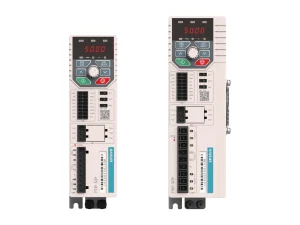 ES210 | Single-Phase Compact VFD | 0.4–2.2 kW | 1-Phase 220 V in, 3-Phase out | Fractional ventilation fans, commercial exhaust blowers, and single-phase supply applications. |
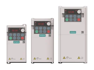 ES230 | Compact Multi-Function | 0.4–11 kW | 220–240 V / 380–415 V | Compact commercial ventilation, supply blowers, and packaged rooftop units. |
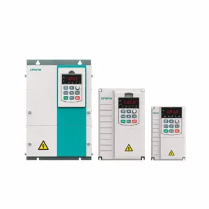 ES300 | Sensorless Vector VFD | 0.75–710 kW | 3-Phase 380–415 V (±15%) | Industry workhorse for heavy industrial blowers, cooling tower fans, and central ventilation systems. |
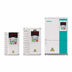 ES500 | High-Performance Vector | 0.75–710 kW | 3-Phase 220–240 V / 380–415 V | Advanced adaptive PID regulation, multi-signal feedback, and high dynamic stability across demanding exhaust lines. |
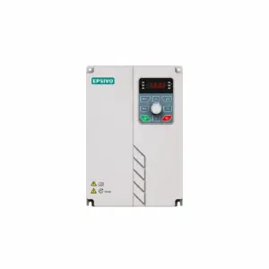 ES530 | Through-Wall Mount VFD | 15–400 kW | 3-Phase 380–415 V (-15%~+10%) | Through-wall mounting allows external heatsink venting, ideal for high-power ventilation control rooms. |
All series feature built-in PID controllers and programmable skip frequencies to protect fan structures from mechanical resonance.
Frequently Asked Questions About VFD Fan
How does a VFD work on a fan?
A VFD for a fan is an electronic motor controller. It rectifies AC utility power into DC, smooths it on the DC bus, then inverts it into variable-frequency AC. Motor speed follows output frequency directly, allowing airflow and duct static pressure to match real-time demand.
How does a VFD affect the fan curve and CFM?
Slowing fan speed shifts the entire fan performance curve downward. The operating point—where the fan curve intersects the duct system resistance curve—moves toward lower airflow (CFM) and lower static pressure, reducing power consumption by the cube of speed.
How low can you safely turn down a fan with a VFD?
There is no universal minimum speed. Safe turndown limits depend on fan aerodynamics, motor cooling (shaft fans lose cooling efficiency at low RPM), bearing lubrication, and system resonance bands. Typical variable air volume systems operate down to 15–20 Hz (30%–40% speed).
Can a VFD do temperature preset plus manual full-speed override?
Yes. Epsivo drives support multi-speed digital inputs and fire-mode override logic. An automated temperature-controlled PID loop can govern daily speeds, while a dedicated digital input switch can force immediate full-speed operation with highest priority during emergency purge.
Where should a VFD be located relative to a fan?
The drive should be located in a clean, ventilated electrical room or inside an appropriately rated enclosure near the motor. If motor cable runs exceed 50 meters, install an output line reactor (dV/dt filter) to mitigate voltage spikes and protect winding insulation.
Why do cooling tower fans have VFDs?
Cooling demand fluctuates continuously with ambient wet-bulb temperature and chiller thermal loading. A VFD modulates fan RPM smoothly to hold basin water temperatures steady, avoiding the heavy cycling, belt wear, and water splashing caused by across-the-line starters.
How much energy does a VFD save on an industrial fan?
Energy savings depend on baseline operating hours and time spent at reduced airflow. Because fan power follows the cubic affinity law (Power ∝ Speed³), a 20% reduction in fan speed yields approximately 50% electrical power savings, achieving commercial payback within 6 to 18 months.