
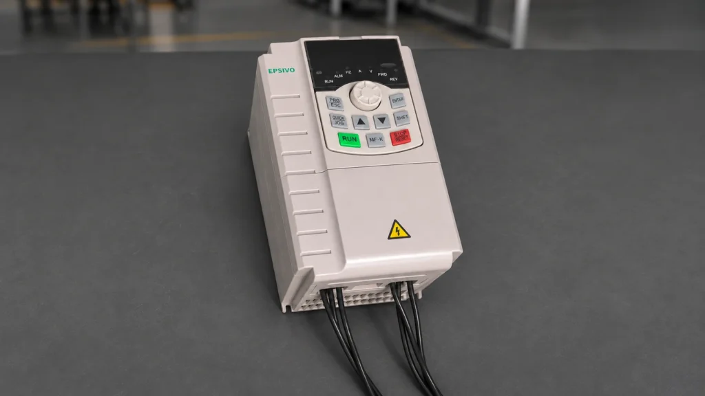
Single-Phase Supply vs. Single-Phase Motors: Key Technical Distinctions
A single phase vfd addresses two completely distinct engineering scenarios that are frequently conflated by equipment operators: directly controlling a true single-phase motor (Route A), or converting a single-phase AC utility supply into three-phase power to drive an industrial motor (Route B). Identifying which route your machinery requires is the essential first step before ordering any drive.
- Route A: Single-Phase Supply In → Single-Phase Motor Out: The drive connects to single-phase utility power and regulates the speed of a single-phase induction motor (permanent split capacitor or shaded-pole design).
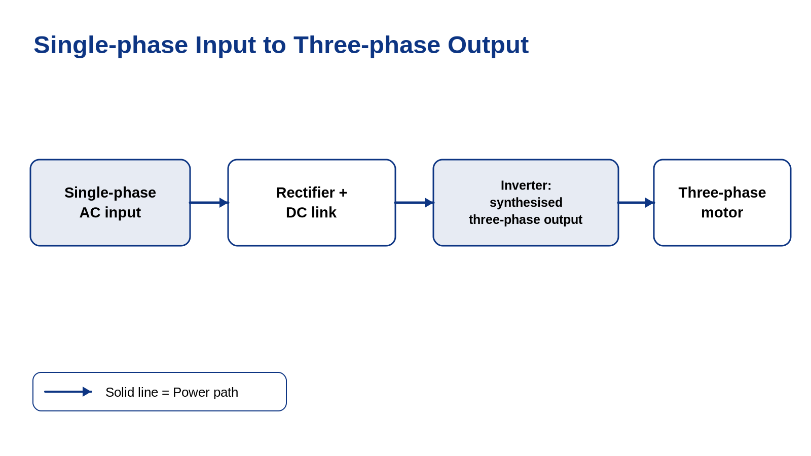
- Route B: Single-Phase Supply In → Three-Phase Motor Out: The drive connects to a single-phase utility feed (110 V or 220–240 V) and internally converts that power to balanced three-phase AC electricity to drive an industrial three-phase motor.
Over 80% of commercial and workshop buyers searching for a single phase vfd actually need Route B: they possess standard residential or light-commercial single-phase power, but wish to operate a heavy-duty three-phase motor on a lathe, milling machine, table saw, or compressor. Understanding this distinction prevents purchasing the wrong drive topology.

What Is a Single Phase VFD?
A single phase VFD is a solid-state power electronic motor controller engineered to regulate motor speed from single-phase utility mains.
Whether utilized for Route A or Route B, the drive rectifies incoming single-phase alternating current into direct current, smooths it on an internal DC bus capacitor reservoir, and inverts that voltage back into alternating current at user-commanded frequencies.
Traditional approaches to operating machinery on single-phase supply relied on rotary phase converters or mechanical variable-pitch pulleys. Solid-state variable frequency drives eliminate the heavy idle power consumption, mechanical vibration, and broad maintenance overhead of older rotary methods, providing sub-hertz speed accuracy, programmable acceleration ramping, and electronic overload protection.
Route A: Controlling a True Single-Phase Motor
Attempting to regulate the speed of a single-phase electric motor requires extreme caution due to internal motor design limitations:
Internal Centrifugal Switch Burnout Risk:
Many single-phase motors (capacitor-start) contain internal mechanical centrifugal switches that disconnect starting windings once the motor reaches ~75% speed. When a VFD slows the motor below this threshold, the switch re-closes, keeping the high-current start winding energized and burning out the motor within minutes.
Severe Low-Speed Torque Degradation:
Single-phase motors rely on auxiliary phase-shift capacitors to produce starting torque. As operating frequency decreases, capacitor reactance increases, collapsing the rotating magnetic field and causing high motor vibration and stalling under load.
Permissible Single-Phase Motor Types:
Speed regulation on single-phase motors is viable only on Permanent Split Capacitor (PSC) or shaded-pole motors driving variable-torque loads (fans and blowers) where starting torque demands are very low.
In most industrial workshops, replacing an older single-phase motor with a standard 3-phase motor and pairing it with a Route B drive provides dramatically superior reliability, torque, and efficiency.
Route B: Converting Single-Phase Input to Three-Phase Output
Route B represents the standard, robust industrial solution for running machinery on single-phase electrical service:
Superior Three-Phase Motor Characteristics:
Industrial three-phase motors do not have centrifugal switches, capacitors, or brushes. They generate smooth, continuous rotating magnetic fields, delivering 100% rated torque down to near-zero speed.
Clean Solid-State Phase Synthesis:
The drive synthesizes three balanced AC lines with exactly 120 electrical degrees of phase displacement, giving the motor identical operating conditions to a three-phase utility feed.
Dedicated vs. Derated Standard Drives:
For motors up to 2.2 kW / 5.5 kW, dedicated single-phase drives (Epsivo ES210 / ES230) connect directly without derating. For larger horsepower ratings, standard three-phase drives can be applied with a 50% derating factor.
For detailed terminal rewiring (220V Delta vs. 380V Star) and dynamic braking resistor sizing for lathes and mills, explore our complete single phase to 3 phase VFD engineering guide.
Decision Matrix: How to Choose Route A or Route B
Use this engineering decision matrix to determine whether Route A or Route B is the correct match for your equipment:
- If your motor has 3 or 4 wires in the terminal box (U, V, W, PE) and nameplate indicates 3-Phase: Select Route B immediately. This is the ideal setup, providing 100% rated shaft torque, variable speed control, and smooth electronic braking.
- If your motor has a start capacitor and centrifugal switch (clicks when spinning down): Do NOT attempt to install a standard VFD. Replace the motor with a standard 3-phase induction motor and select a Route B drive.
- If your motor is a permanent split capacitor (PSC) fan or pump with no mechanical switch: Route A speed control is possible within a limited turndown window (typically 35–50 Hz), provided starting torque demands are modest.
- If your facility powers auxiliary hydronic or pneumatic equipment: Route B phase-conversion drives can also power three-phase centrifugal booster pumps and industrial ventilation fans seamlessly from residential single-phase lines.
How to Select a Single Phase VFD: Motor Nameplate & Wiring Checklist
Follow this five-point engineering checklist to verify electrical compatibility before purchasing:
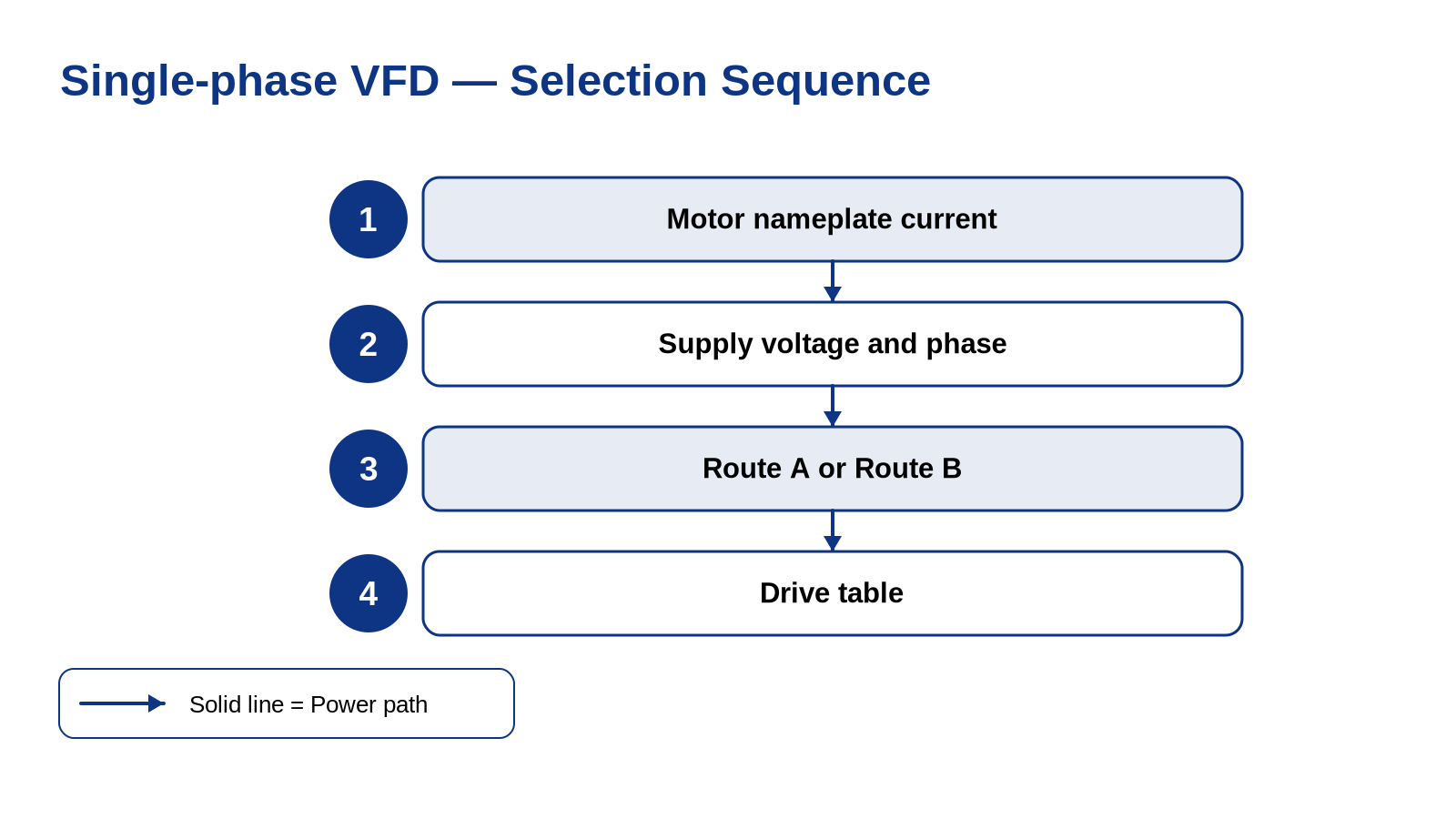
Examine Motor Nameplate Rated Voltage:
Confirm whether the three-phase motor nameplate lists dual-voltage ratings (220V Δ / 380V Y or 230V Δ / 400V Y). A 220V single-phase drive can only supply 220V three-phase output.
Size Exclusively by Full Load Amperage (FLA):
Read the rated current at operational voltage. Ensure drive continuous rated output current equals or exceeds motor FLA. Never select by motor horsepower alone.
Calculate Upstream Single-Phase Breaker Capacity:
Single-phase input current is approximately 1.73 times higher than three-phase motor current. Ensure the workshop utility breaker and branch wiring can handle the input amperage without nuisance trips.
Check Machine Tool Spindle Braking Requirements:
If driving a metal lathe, milling machine, or saw, ensure the VFD includes a built-in dynamic braking chopper and connect an external braking resistor to eliminate overvoltage trips during rapid stops.
Verify Physical Enclosure and Ambient Cooling:
Ensure the drive chassis has adequate clearance for airflow. For dusty workshop environments with metal shavings, install the drive inside a sealed ventilated control enclosure.
Always verify that the motor can be configured in Delta (Δ) 220 V before pairing with a 220 V single-phase VFD.
Epsivo VFD Series for Single-Phase Supply
Epsivo provides dedicated single-phase input drives and vector control drives for light industrial and commercial workshops:
| Series | Platform | Power Range | Input Voltage | Single-Phase Application Fit |
|---|---|---|---|---|
 ES210 | Single-Phase Compact VFD | 0.4–2.2 kW | 1-Phase 220 V in, 3-Phase out | Primary single-phase drive for 220 V supply; dedicated Route B phase conversion for small workshop machinery, ventilation, and pressure pumps up to 2.2 kW. |
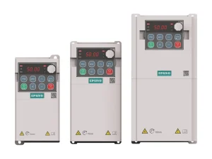 ES230 | Compact Multi-Function | 0.4–11 kW | 220–240 V / 380–415 V | Compact multi-function drive supporting single-phase 220–240 V input (0.4–5.5 kW); delivers sensorless vector control for compact machinery and conveyors. |
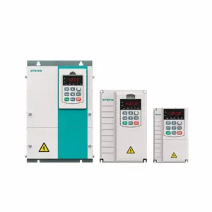 ES300 | Sensorless Vector VFD | 0.75–710 kW | 3-Phase 380–415 V (±15%) | Industrial sensorless vector drive; supports single-phase power conversion across medium industrial loads when derated by 50% continuous output current. |
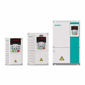 ES500 | High-Performance Vector | 0.75–710 kW | 3-Phase 220–240 V / 380–415 V | High-performance vector drive with adaptive PID, advanced torque regulation, and comprehensive fault protection for demanding conversion installations. |
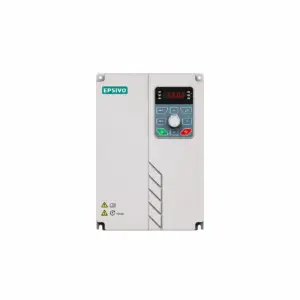 ES530 | Through-Wall Mount VFD | 15–400 kW | 3-Phase 380–415 V (-15%~+10%) | Through-wall mounting drive with isolated cooling channel for dust-laden single-phase workshops and industrial control rooms. |
ES210 series is specifically engineered for single-phase 220 V input, driving three-phase 220 V motors without output derating.
Frequently Asked Questions About Single Phase VFD
What is a single phase VFD?
A single phase VFD is a variable frequency drive powered by single-phase AC utility electricity. It can either be designed to regulate specific single-phase motors (Route A) or, much more commonly, to convert single-phase input power into balanced three-phase output power to run standard industrial three-phase motors (Route B).
Can you put a VFD on a single-phase motor?
Only on specific motor types without mechanical switches. Permanent Split Capacitor (PSC) and shaded-pole motors driving low-starting-torque loads (like fans) can be modulated with specialized drives. Motors with centrifugal starting switches must not be used with VFDs because low-speed operation keeps start windings engaged and causes rapid burnout.
What is the difference between Route A and Route B?
Route A takes single-phase power in and outputs single-phase power to control a single-phase motor. Route B takes single-phase power in and converts it to balanced three-phase power to drive a standard three-phase motor. Route B is vastly preferred for machine tools, pumps, and compressors because three-phase motors offer higher efficiency and 100% full torque down to low speeds.
Why does single-phase input require larger electrical wire?
Because electric power is the product of voltage, current, and phase factor. To deliver the same mechanical shaft power from a single-phase supply as from a three-phase supply, single-phase input current is roughly 1.73 times higher. For example, a 2.2 kW motor drawing ~9A on 220V 3-phase draws approximately 15A on single-phase 220V input.
Does a single phase VFD decrease motor horsepower?
When using a dedicated single-phase drive (such as Epsivo ES210) driving a three-phase motor rewired in Delta (Δ) 220V, there is zero reduction in motor horsepower—the motor develops 100% of its rated torque and power. A derating factor is only required when repurposing a standard three-phase drive to run on single-phase mains.