
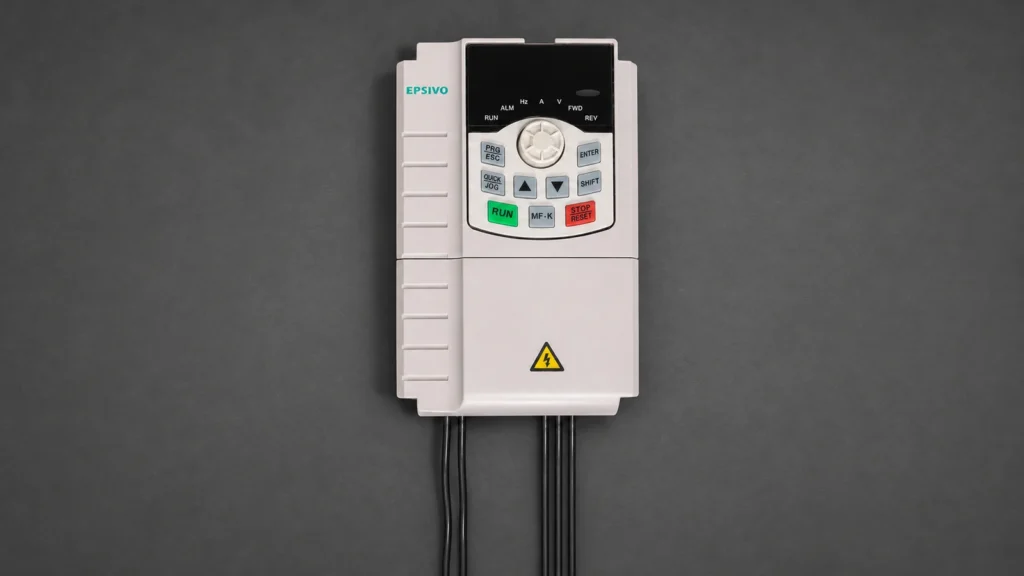
What Is a Single Phase to 3 Phase VFD?
A single phase to 3 phase vfd is a solid-state power electronic converter that accepts residential or light-commercial single-phase AC utility power and generates a fully balanced, variable-frequency three-phase AC output. This allows workshops and small manufacturing facilities to operate heavy-duty three-phase machine tools, pumps, and compressors without purchasing an expensive utility line drop.
By eliminating the idle power losses and acoustic roar of mechanical rotary phase converters (RPCs), and avoiding the severe 33% torque degradation of static phase converters, a solid-state single phase to 3 phase vfd delivers 100% rated shaft torque, variable spindle speed control, and smooth acceleration ramping.
It is essential to clarify that a phase-conversion drive is designed to power a three-phase motor from single-phase utility mains. If your mechanical load is an existing single-phase motor with run capacitors, refer to our companion technical guide on single phase VFD drives to select the correct control topology.
How Phase Conversion Works: Rectification, DC Bus & Inversion
A VFD achieves phase conversion through complete decoupling of the incoming AC power waveform into direct current before synthesizing three output phases:

Single-Phase Rectification to Direct Current:
Incoming single-phase AC passes through the input bridge rectifier, charging internal DC bus capacitors to a peak voltage equal to Vrms × 1.414 (approximately 310–330 V DC for a 230 V utility feed).
DC Bus Energy Storage and Ripple Filtering:
Because single-phase AC delivers power pulsing at 100 Hz or 120 Hz, the DC bus capacitor bank absorbs heavy ripple current, acting as a massive energy reservoir to maintain smooth DC voltage.
Three-Phase Inverter Bridge Pulse-Width Modulation:
Six high-speed IGBT transistors fire under microprocessor vector algorithms to synthesize three distinct sinusoidal PWM output voltage lines (U, V, W) with precise 120-degree phase displacement.
Because the output AC waveforms are synthesized independently by the microprocessor, the drive produces three balanced phases spaced 120 electrical degrees apart, regardless of input phase count.
Dedicated-Input Drives vs. Derated Standard Three-Phase Drives
When selecting a single phase to 3 phase VFD, engineers and workshop operators have two distinct hardware paths:
- Dedicated Single-Phase Input Drives (e.g., Epsivo ES210 / ES230): Engineered specifically for single-phase utility connections. Their input diode bridges and DC bus capacitors are oversized at the factory to handle the higher RMS ripple current inherent to single-phase feeds. You select these drives directly based on motor nameplate full-load current without applying any mathematical derating factor.
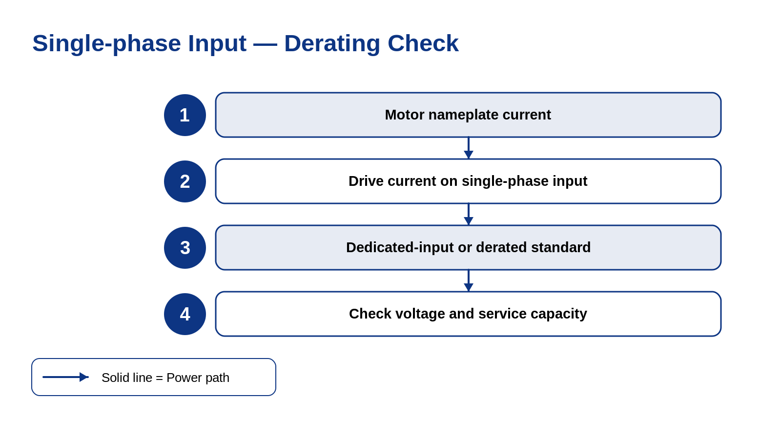
- Standard Three-Phase Drives on Single-Phase Power (e.g., Epsivo ES300): For loads above 5.5 kW where dedicated single-phase drives are unavailable, standard 3-phase drives can accept single-phase power across two input terminals (R and T). Because only 4 rectifier diodes conduct, continuous output current must be derated by 50% (e.g., a 15 kW drive powers a 7.5 kW motor).
Voltage Matching & Terminal Configuration: 220V Delta vs. 380V Star
A fundamental electrical constraint of standard VFDs is that output voltage cannot exceed input supply voltage. Follow these rewiring rules:
The Voltage Passthrough Rule:
A standard VFD does not step up voltage. Supplying 220 V single-phase power produces a maximum three-phase output of 220 V line-to-line. It CANNOT generate 380 V or 415 V three-phase electricity unless paired with an upstream step-up transformer.
Inspect the Motor Terminal Box Nameplate:
Examine the motor connection diagram. Most industrial induction motors under 5.5 kW feature dual-voltage ratings, such as 220V Δ / 380V Y or 230V Δ / 400V Y.
Reconfigure Jumper Links to Delta (Δ) Connection:
If the motor was previously wired in Star (Y) for 380 V grid power, open the terminal box and rearrange the brass jumper links into parallel Delta (Δ) configuration. This matches motor windings to the 220 V three-phase output generated by the drive, delivering 100% rated shaft torque.
Never attempt to drive a 380 V/400 V Star-only wound motor directly from a 220 V single-phase VFD; the motor will suffer severe torque starvation and overheat.
Dynamic Braking & Resistor Sizing for Machine Tools
Machine tools like metal lathes and vertical mills carry high rotational inertia requiring dynamic braking:
Stopping a 2,000 RPM spindle or reversing during threading causes the spinning chuck to act as a flywheel. The motor regenerates energy back into the drive DC bus.
Without an external braking resistor, this surge triggers DC bus overvoltage (OV) faults, allowing the spindle to freewheel. Wiring a braking resistor across terminals B1 and B2 lets the internal braking chopper dissipate kinetic energy as heat, stopping chucks within 1 to 3 seconds.
When NOT to Install a VFD on Machine Tools
A VFD powers motors directly; it cannot be wired as a universal machine wall outlet:
- Never Wire Upstream of Mechanical Switches: Opening or closing mechanical drum switches between an energized VFD and motor creates voltage arcing that destroys drive IGBTs. Wire operator switches directly to VFD digital logic inputs (FWD / REV / STOP).
- Never Power Control Transformers or Solenoids from VFD Output: Machine tool work lights, 24V coolant solenoids, and magnetic coils will burn out on synthesized PWM power. Power them directly from single-phase utility mains.
- Mechanical Clutch Lathes: On clutch-operated lathes where motors run continuously, keep the VFD at fixed frequency and change speeds mechanically.

Pre-Installation Engineering Checklist
Complete this engineering checklist before commissioning your phase conversion drive:
Confirm Motor Nameplate FLA:
Ensure VFD continuous output amps equal or exceed motor nameplate FLA at 220 V. Reconfigure jumpers to Delta (Δ).
Size Upstream Breakers for 1.73x Current:
Single-phase input current is ~1.73 times higher than three-phase motor current; size branch circuit wiring accordingly.
Wire Control Switches to Digital Inputs:
Connect run, stop, and reverse pushbuttons to low-voltage digital inputs (DI1, DI2, COM) using shielded wiring.
Configure Braking Chopper Parameters:
Enable dynamic braking parameters when using an external resistor to prevent spindle overvoltage trips during fast deceleration.
Phase-conversion drives pair with workshop equipment, including rotary screw air compressors, coolant delivery pumps, and exhaust ventilation blowers.
Epsivo VFD Series for Phase Conversion
Epsivo offers dedicated single-phase input drives and heavy-duty vector drives engineered for workshop phase conversion:
| Series | Platform | Power Range | Input Voltage | Phase Conversion Suitability & Fit |
|---|---|---|---|---|
 ES210 | Single-Phase Compact VFD | 0.4–2.2 kW | 1-Phase 220 V in, 3-Phase out | Dedicated single-phase 220 V input, three-phase 220 V output without derating; ideal for small lathes, milling machines, and workshop equipment up to 2.2 kW. |
 ES230 | Compact Multi-Function | 0.4–11 kW | 220–240 V / 380–415 V | Dual-rated compact drive supporting single-phase 220–240 V input (0.4–5.5 kW) with sensorless vector control for medium workshop machinery. |
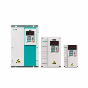 ES300 | Sensorless Vector VFD | 0.75–710 kW | 3-Phase 380–415 V (±15%) | Standard 3-phase 380–415 V vector drive; can be powered from single-phase utility when derated by 50% continuous output current. |
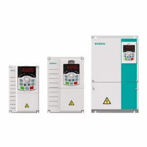 ES500 | High-Performance Vector | 0.75–710 kW | 3-Phase 220–240 V / 380–415 V | High-performance vector drive supporting single-phase input derating up to large capacity for custom phase-conversion control panels. |
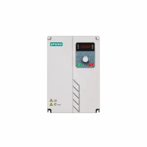 ES530 | Through-Wall Mount VFD | 15–400 kW | 3-Phase 380–415 V (-15%~+10%) | Through-wall mounting drive with isolated heatsink cooling for enclosed workshop phase conversion cabinets. |
ES210 and ES230 series feature dedicated single-phase rectifiers designed for 220–240 V utility service without requiring output current derating.
Frequently Asked Questions About Single Phase to 3 Phase VFD
Can a VFD convert single-phase power to three-phase power?
Yes. A VFD designed for single-phase input rectifies single-phase AC to direct current (DC), filters it across the DC bus, and uses IGBT transistors to synthesize balanced three-phase AC output with 120-degree phase separation.
Can a 220V single-phase VFD run a 380V three-phase motor?
Only if windings can be reconfigured. Most motors under 5.5 kW are dual-voltage (220V Delta / 380V Star). Rearranging terminal jumpers into Delta (Δ) lets the motor run at full torque from a 220V drive. Star-only motors require a step-up transformer.
How much should a standard 3-phase VFD be derated when powered by single phase?
When using a standard three-phase drive (such as ES300) on a single-phase supply, continuous rated output current must be derated by 50% due to increased thermal loading on 4 of the 6 input diodes. Dedicated single-phase drives (such as ES210) require zero derating.
Why does my lathe trip the VFD when stopping rapidly?
Rapid deceleration of a heavy chuck causes the motor to act as a generator, dumping kinetic energy back into the DC bus and causing an overvoltage (OV) fault. Installing a dynamic braking resistor across terminals B1 and B2 safely dissipates this regenerative energy as heat.
Can I use one VFD to power my entire workshop wall receptacles?
No. A VFD is a dedicated motor controller synthesizing PWM power; it is not an AC grid utility substitute. Connecting transformers, fluorescent ballasts, solenoids, or downstream mechanical contactors to a VFD output will destroy drive IGBTs.
Is a single-phase to 3-phase VFD better than a rotary phase converter?
For individual machine tools, pumps, and compressors, a VFD is far superior. It provides variable speed control, soft starting, electronic braking, and high efficiency without the continuous idle electricity waste, vibration, and maintenance of a rotary phase converter.